Machines that need an oil cooler are generally those that are required to operate outside the parameters that they were originally designed for.
For example,
A. An internal combustion engine modified to produce more power.
B. A Transmission Required to Transfer more Torque.
C. Racing Applications or Extended High Duty cycles where high power is applied for extended periods of time.
D. A machine designed for operation and use in Northern Europe or North America but sent to operate in hot humid and or tropical environments.
All Oil is designed and formulated to operate effectively within a certain minimum and maximum temperature range. If you operate a piece of equipment for extended periods of time at high loads excess heat is generated and the oil's temperature will rise. If the oil's maximum designed temperature range is exceeded you will experience some or all of the following eleven problems.
1. Shorter Oil Life
Hydraulic Oils or Transmission Oils operating at temperatures above 65°C (150°F) will start to deteriorate at an accelerated rate, this will result in shorter oil change periods. For Example having to change your Hydraulic System's oil every 1000 hours instead of 1500 hours or your transmission oil every 15,000 KM instead of 30,000 KM. Result more money spent on Oil and filters.
2 Gasket and Seal Damage
Hot Oil damages Gaskets and Seals and this may result in Internal as well as External Leaks.
3. Internal Leaks
Internal leaks reduce efficiencies, power and or torque of hydraulic cylinders, pumps and motors and in the case of a transmissions may cause erratic performance, slow acceleration and or gear shifting.
Internal leaks reduce efficiencies, power and or torque of hydraulic cylinders, pumps and motors and in the case of a transmissions may cause erratic performance, slow acceleration and or gear shifting.
4. External leaks
External Leaks can make a mess of your mobile equipment as leaks are blown all over the underside of your vehicle, dust and grime will then stick to the oily components creating an ugly sticky mess requiring cleaning.
External Leaks can make a mess of your mobile equipment as leaks are blown all over the underside of your vehicle, dust and grime will then stick to the oily components creating an ugly sticky mess requiring cleaning.
5. Dangerous Slip Hazards
Oil leaking or dripping onto a non absorbent floor or road not only makes a mess but also creates a potentially dangerous slip hazard that may result in an automotive accident with personal and property damage and possible prosecution.
6. Fines for Environment damage and Pollution
Oil Leaks onto the ground could be interpreted as contamination and pollution and you risk being fined. The actual or perceived risk of environmental impact from an oil leak is real, so stop that leak or at the least clean it up and save yourself the potential of legal action and a fine or imprisonment!
A recent Client of ours was sent a clean up bill for AU$3,500 when their excavator was left unattended and unchecked over the weekend leaking hydraulic oil into the ground on a particularly sensitive government construction site.
7. Mechanical Damage
Large external leaks if left unchecked will reduce or deplete the oil level of the hydraulic oil circuit causing excess friction and even more heat generation, poor performance, and eventually catastrophic mechanical damage.
7. Mechanical Damage
Large external leaks if left unchecked will reduce or deplete the oil level of the hydraulic oil circuit causing excess friction and even more heat generation, poor performance, and eventually catastrophic mechanical damage.
8. Poor Efficiency
Lastly the Hydraulic system's efficiency is reduced because the oil viscosity changes (usually gets thinner) and more power losses are experienced resulting with even more heat being generated with reduced machine performance and or productivity.
If on the hand you operate a piece of equipment at UNDER the oil's designed temperature range you risk the following problems.
9. Poor Oil Flow when oil is too cold.
An oil that is designed to operate 10°C to 40°C ambient temperatures will be too thick to flow properly a -5°C, This can cause the machine's oil pump to cavitate which causes accelerated mechanical wear and contamination in the oil.
When a pump cavitates it is not actually pumping as much oil volume as it was designed to do and therefore not enough oil will reach critical mechanical components to produce drive, support loads, reduce friction and or carry heat away. The result is accelerated mechanical wear and or damage.
11. Temperature Control and Design.
As with internal combustion engines that have water cooling and thermostats that control temperature to a relatively narrow range, thermostat control is also available for oil cooler systems to provide quick warm up and or cooling down but are also designed to prevent over cooling. 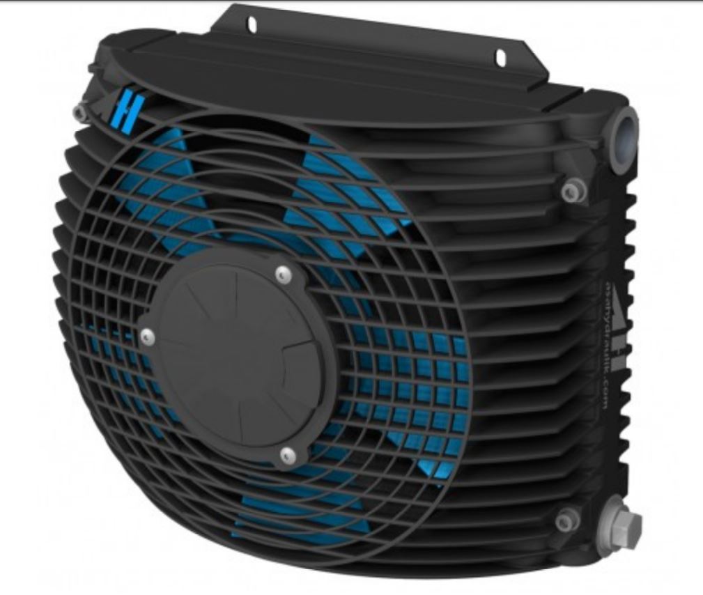 |
| ASA Hydraulik LL 06 Oil Cooler with 12 Volt DC Fan Capable of Cooling an Oil flow of up to 50 Lt/Min with a P spec = 0.11 kW/°C and pressure drop 0.5 bar with a Max oil Pressure of up to 26 Bar. |
How to Calculate the Size of an Oil / Air Cooler.
When there is power transfer, friction or a resistance to oil flow, pressure as well as heat are generated. The temperature of an oil in a circuit will continue to increase until the added thermal energy has the same value as the combined radiation and convection energy absorbed by the surrounding atmosphere.
After a certain operating time the oil temperature rise will eventually slow and then stabilize.
If this stabilized oil temperature is too high, the oil must be cooled because Hot Oil will Cost you in repairs, a slow job, or a lost race!
In order to choose the required cooler type we must know the required cooling performance.
How to find out the required Oil Cooling requirement.
Warning, some mathematics follows below, it looks complicated
but really it isn't.😅
If it all seems to complicated and hard please contact us.😉
Example A. Existing Hydraulic circuits.
Use the formula that takes the rise in Temperature of a known volume of oil over a known time frame.
For existing Hydraulic / Oil circuits the heat input to the oil can be accurately determined if the rise in the Oil's temperature is measured over a certain period of time. This then gives the amount of heat to be exchanged by the cooler in order to maintain the system at an optimum operating temperature.
PK = m x c x (t2 – t1) / 1000 x T
PK = required cooling performance [kW]
m = Weight or mass of the oil in reservoir [kg] (see below for how to calculate this)
c = specific heat capacity [Wh/kg°C]
(c ~ 0.53 for hydraulic oil, c ~1.16 for water)
t1 = oil temperature at the begin [in °C]
t2 = oil temperature at the end [in °C]
T = heat up time [hours]
To Quickly Calculate the Oil weight or Mass (in Kilo Grams) of the hydraulic oil in a tank use the following formula.
Length x Width x Height of tank in cm then multiply by 0.00088
For Example If a hydraulic tank on a 8 ton excavator was 40 cm long, 30 cm wide and 60 cm high then 40 x 30 x 60 = 72000 cm³
72000 x 0.00088 = 63.36 KG
For Volume of Cylindrical Tanks
measure the diameter D and length or height H in cm and then use the following Formula
V= πD²H/4
Eg Worked example for the excavator's tank dimensions above.
PK = required cooling performance [kW]
m = Weight or mass of the oil in reservoir [kg] 63.36
c = specific heat capacity [Wh/kg°C] 0.53
t1 = oil temperature at the begin [in °C] 25
t2 = oil temperature at the end [in °C] 113
T = heat up time [hours] 45 minutes = 45/60 = 0.75 hours
PK = m x c x (t2 – t1) / 1000 x T
PK = 63.36 x 0.53 x (113-25) / 1000 x 0.75
PK = 33.58 x (88) = 2955 / 750
PK = 3.94 KW
P spec = PK / (T oil – TL)
P spec = specific cooling performance in (kW/°C)
PK = required cooling performance [kW]
T oil = oil temperature inlet (°C) (desired temperature)
T L = air temperature inlet (°C) (maximum expected temperature)
P spec = 3.94 / (60-40)
P spec = 3.94 / 20
P spec = 0.197 kW/°C
If you are not confident in doing the math yourself, Very similar numbers can be generated, by using ASA Hydraulik secure online calculator. Try this Application to assist you in calculating the right size and model of oil cooler.
Online Oil Cooler Calculator
Online Oil Cooler Calculator
Or
Contact Us for real live Human to Help & Assist you.
By entering the following information detailed below a range of suitable oil coolers will eventually be displayed.
(We have used example figures obtained from an over heating excavator in the worked example below )
Contact Us for real live Human to Help & Assist you.
By entering the following information detailed below a range of suitable oil coolers will eventually be displayed.
(We have used example figures obtained from an over heating excavator in the worked example below )
- Pump or System Oil flow in Liters / minute = 40 L/min
- Altitude above sea level = 50 m
- Oil Type = ISO VG 68
- Desired oil temperature at inlet = 60°C
- Maximum cooling air inlet temperature = 40°C
as well as (see below)


as well as
- Cooling fan Voltage DC, AC or Hydraulic driven = we choose DC
- Maximum Noise of Cooling Fan. = 85 dB

Details of model ASATT11RD01 were extracted from ASA catalog with the following oil cooler data.
- Dimensions 340 mm High x 380 mm Wide x 175 mm Deep
- Oil in out port centers 255 mm
- 3 mounting holes each side 100 mm apart
- Weight 8.7 KG
- Cooling fan power 12V DC, 20.8 amps, 0.27 KW
- Fan Motor protection, IP 68
- Air Flow 0.62 kg/second
- Noise 77 dB

Another Approximate calculation The required cooling performance PK can generally be calculated as in the following formula
PM = p x Q oil / 600 x η
and then use
PK = PM (1 – η)
where as
η = general Pump Efficiency (70% efficiency use the value of 0.7)
PK = required cooling performance [kW]
PM = required motor power [kW]
p = oil pressure [bar]
QP = oil flow [l/min]
As a guide hydraulic circuits with constant flow pumps have a general efficiency from approximately 70-75%,
therefore use a η of = 0.7 to 0.75
Circuits with variable Flow pumps have a general efficiency from approximately 75 to 80% therefore use an : η = 0.75 to 0.80.
Selection of the cooler:
After you have calculated the required cooling performance (PK ) using one of the above formulas, the specific cooling performance (Pspec) must now be determined.
Pspec = PK / toil – tL (kW/°C)
Pspec = specific cooling performance (kW/°C)
Toil = oil temperature inlet (°C)
TL = air temperature inlet (°C)
Once you have these values you can then compare various charts listed below to get the required size of cooler.
 |
| Performance Characteristics of ASA Hydraulik LL 06 12 Volt DC Fan Ventilated Oil Cooler. |

No comments:
Post a Comment